Holcomb Energy System (HES) – free energy


Holcomb’s story of a good idea
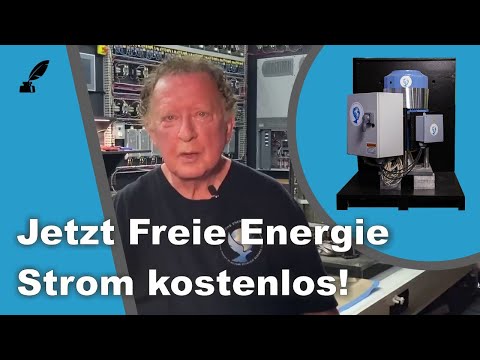
When we first heard about a solid-state generator from the USA, we could not imagine how it would be possible to generate electricity with magnetism and coils without mechanical work. Dr Robert Holcomb told us that he carried this idea around with him for more than 20 years and eventually began to put his thoughts into practice in his workshop. His first developments still had rotors, but once he had recognised the principle within the models, the first solid-state models logically followed – that is, there were no more moving parts. Here is a video (German) in which Dr Robert Holcomb explains how it works.
Note on a Ukrainian source
We have taken the following explanations from a Ukrainian blog run by Serge Rakarsky. The original from 2022 can be found here. Serge Rakarsky obviously has profound knowledge of electrical engineering. Since he has also researched very well and our Russian is a little rusty, we offer a German page here, with partly updated additions, including our own original pictures from Sarasota, Florida.

Not a new idea
Let’s begin with an episode from history: the development of an electromagnetic solid-state converter.
At the beginning of the 20th century, the Spanish engineer Clemente Figuera presented the world with a solid-state generator/converter (without physical rotation of the rotor-stator). This was the first patent and working model, in 1902. The second patent followed in 1908. The rights to the first patent and the working model were bought by the management of an international bank for 60 million pesetas (equivalent to 320 kg of gold) in order to bury them. The acquired patent was not allowed to become generally available. The engineer did not survive the second publication. I note that there is nothing surprising or particularly mysterious about this technology, which is why it is not at all clear why 114 years passed before Figuera’s ideas were turned into a practical working model.
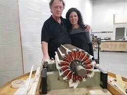
In 2020–21 a system appeared, named after the surname of its inventor Robert Holcomb: the Holcomb Energy System. Holcomb Scientific Research presents a new emission-free energy source: launch party video on YouTube
A new energy source
Holcomb Scientific Research Ltd. (HSR), a research and development company, announced a scientific breakthrough in generating 100 per cent clean energy with the launch of the Holcomb Energy System (HES). HES consists of a series of innovative, patented technologies and represents an entirely new source of genuine power generation, capable of tackling critical global challenges such as climate change, pollution and universal access to electricity.
Tested and certified
By using previously untapped electron spin energy in electrical steel, HES makes external energy sources such as sun, wind or fossil fuels unnecessary. The products are tested and certified – certified by SGS and DNV-GL, the world’s leading testing, inspection and certification companies – and are certified to UL and NEC (National Electrical Code) standards. The technology may not be the holy grail of perpetual motion that Nikola Tesla suspected, but if Holcomb Scientific Research’s claims about its HES systems prove true, the technology could be a useful addition to the power generation market.
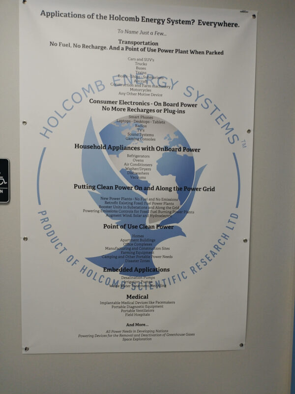
Measurements confirm overunity
First concrete test installations in companies
HES systems are reported to be already supplying an industrial site and two further 2,400-square-metre commercial properties with electricity. Company website: holcombenergysystems.com
Dr Holcomb’s patents:
- A small selection: patents.justia.com/inventor/robert-ray-holcomb
- US20120007708A1
- US20190238011A1
- WO2018134233A2
- WO2021063522A1



Rotating the magnetic field with relays

So far, only the rotation of a constant magnetic field without physical rotation of the magnet rotor has been organised, by switching the electromagnets step by step according to a proven algorithm. The basis for the development of Robert Holcomb’s generator was the development of a solid-state rotor.
How the generator works
Robert Holcomb’s synchronous solid-state machine works according to the algorithm of a conventional electromechanical synchronous power generator.
A solid-state rotor is a system of electromagnets that simulates the effect of a mechanical magnet rotor. The task is to create a constant magnetic excitation flux, maintain it and move it in the stator and rotor, thereby synchronously inducing an EMF (electromotive force) in the generator’s phases. When a load is connected, the excited current in the phase wires strengthens the magnetic field of the system’s magnetic flux. The magnetic flux [ϕ] has a constant component, both for a conventional electromechanical generator and for a solid-state Holcomb machine. Like a synchronous generator, the Holcomb machine depends heavily on the connected load in order to create a working rotating field.
The electric vortex field
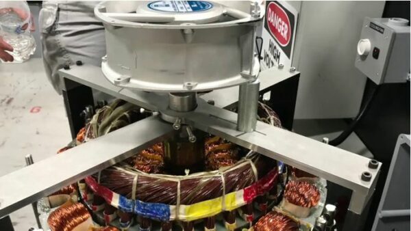
My explanations: let us imagine a conventional synchronous mechanical generator (such as one built into a car). From the study of electromechanics and electrodynamics we learn that an electromechanical generator is a device that converts mechanical rotational energy into electrical energy. I categorically disagree with this statement. Firstly, the Lorentz force can only be explained for an open conductor moving in a magnetic field, or vice versa. In a car generator, the wire is laid in a slot in the magnetic circuit. The movement of the field in the magnetic circuit is explained by a change in the magnetic saturation of the core as the poles of the dipole rotate in the core body.
Designers and physicists explain this through the EMF (electromotive force) in such a generator: the appearance of an electric vortex field around the conductor when the magnetic field parameter changes over time. In stationary conductors, the induced EMF is a consequence of the effect of the electric vortex field on free charges, which arises when the magnetic field changes. The concept of an electric vortex field was introduced into physics in 1861 by the great British physicist J. Maxwell.
Design and calculations
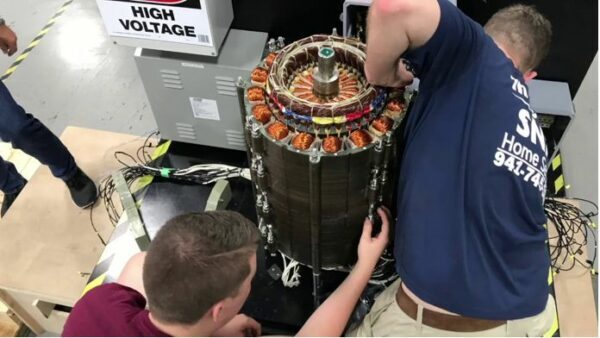
Now let us imagine the design of a generator: a slotted stator in which a three-phase generator winding is installed for a twelve-pole magnet rotor (six pole pairs). The rotor is an electromagnet on an axle with two pole plates with branches that form six poles of one polarity. These branches are bent on the axle towards the centre of the coil so that they form twelve (6X6) electromagnetic poles. When the axle turns, these poles rotate relative to the stator. The magnetic field at the rotor poles is a consequence of the operation of the electromagnet, which has its own power consumption.
The on-board voltage is 12 volts, the maximum excitation current is 5 amps. Maximum excitation power 12 V * 5 A = 60 watts. To generate a peak value of magnetic induction in the stator, an excitation power of the electromagnet of 60 W is required, compared with the generator’s maximum output of 1.5 kW. The question arises: where does this result come from?
Conversion efficiency
You can read the answer in the physics textbook MAGNETIZATION OF STEEL. Turning the rotor on the shaft by an external mechanical driving force provides a “rotation” of the field or, as with the stator core, a synchronous change of the magnetic field (magnetic induction) at a given point. The reason the generator shaft slows down is the magnetic locking of the electromagnetic attraction between the two electromagnets, rotor and stator. When a phase circuit with a load is closed into a circuit, a current is produced in the wires, which in turn forms the electromagnetic force of the “stator electromagnet”. The electromagnetic attraction forces of rotor and stator are overcome by the generator’s electromagnetic torque. This is the necessary mechanical energy, which is not converted but, through rotation in the generator stator, forms an alternating component of the magnetic induction from the rotor electromagnet. As we can see, we could find no sign of mechanical energy being converted into electrical energy. For the direct conversion of the electrical input excitation power Pr into the output power of the generator phases Pg, we can conditionally ignore it. Here too we can conditionally determine the conversion efficiency:
Efficiency = Pg / Pr = 1.5 kW / 0.06 kW = 25.0 (2,500%)
Mechanical rotation of the magnetic poles in the stator – and if you build a device in which the movement of the field is simulated by switching electromagnets on and off according to a special algorithm? Let us assume the share of costs for excitation rises to 200 W (0.2 kW); in any case the efficiency = Pg / Pr = 1.5 kW / 0.2 kW = 7.5 (750%).
Video: how the Holcomb Energy System works
Read more
My publication is even more extensive than shown here. Go to my website and read the article to the end. Discover the chapters there:
- “The secret of electrical steel”
- “No mechanical energy”
- “Hard for experts to grasp”
- “Various researchers try to implement Holcomb’s patent”
- “The design task that follows from these features”
- “Controlling the magnetic fluxes”
There you will also find book recommendations from the gehtanders shop with further information on this and other interesting topics.
To the article on gehtanders.de (German)

Visit to the USA planned

Organised by Adolf and Inge Schneider (publishers of NET-Journal), the next visit to Holcomb Energy Systems in Sarasota (USA) is planned for April 2024.
As soon as this trip is over and results can be published, we will keep you informed here about the development of this technology.
It remains exciting.
Subscribe to NET-Journal or order a trial copy
“Das geht anders – blog for free energy”
Notes on content provided by authors
Comments
Loading comments …
Become a member to comment publicly. GAIA members write comments in the members' portal — under their nickname, visible to everyone.